

If you are using the Cheetah SPI Host Adapter, but working with a new SPI memory chip (GD25Q80CTIG) that supports Duo and Quad SPI modes, it looks like you need a different approach.
You have been creating XML files for new chips and prototypes – and like the UI of the Flash Center Software from Total Phase. You like the software and would like to continue with Flash Center, what should you do?
Well, the Cheetah SPI Host Adapter does support single SPI mode and is compatible with Flash Center Software. However, to expand the capability to include Duo and Quad SPI modes, we recommend using the Promira Serial Platform with the SPI Active - Level 3 Application. This will allow you to continue using the Flash Center Software to create and modify XML files as needed.
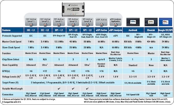
Here’s a chart so you can compare the features of the Promira platform and the Cheetah adapter:
Note: using SPI Active - Level 3 Application requires the installation of SPI Active Levels 1 and 2.
You may find this knowledge base article that shows an example of using the Promira Serial Platform with Flash Center Software to program a QSPI flash, Programming QSPI Flash Using the Promira Serial Platform and the Flash Center Software helpful. This example uses the Micron SPI Flash N25Q032A 1.8V SOIC 8 assembled on the Flash SOIC-8 Socket Board - 10/34. Of course, the steps can be modified for other devices including your SPI chip (GD25Q80CTIG). Following is an overview of the instructions provided in the article.
The commands used:
- Program + Verify - Writes data to one or more attached memory devices and then reads back the data to verify it for correctness.
- Program - Writes data to the device, but without verification.
- Program (No Erase) - A special mode for SPI Flash devices. It writes data to the device, but does not perform an erase cycle.
- Read Device - Reads the contents of the selected device and replaces it in the current contents in the data buffer.
- Verify - Verifies the contents of the selected devices against the contents of the data buffer.
- Erase - Erase the entire memory device or a portion of it.
Adding a Memory Device to the Flash Center Parts List:
- To add a new device, refer to the data sheet of the selected device, enter the device parameters into the XML file and then load in the file.
- If the device is already supported, all you have to do is select the desired device through the Flash Center Software dialog.
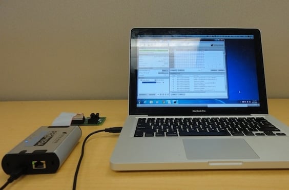
Setting up the equipment:
- Connect the Promira platform USB connector to the USB connector of the computer.
- Connect the Promira platform to the device (this example uses the Flash SOIC-8 Socket Board.
- Launch the Flash Center Software and connect it to the Promira platform.
- Configure the target power for 1.8V.
- Select the target device (refer to Adding a Memory Device to the Flash Center Parts List above).
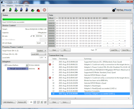
- Select the bit rate and the Quad mode for the SPI device – refer to the Device Control section in Figure 2 below.
Reading and programming the memory device:
- Read the memory device: Click Operations > Read Target
- Program and then read the device: Click Operations > Program + Verify, and then click Operations > Read Target.
The results are shown in the figure below:
 We hope this answers your question. Additional recourses abou the Promira Serial Platform are available here:
