

We often get inquiries from our customers about what slave address to use in order to communicate with their I2C slave device. A lot of this confusion stems from the fact that different vendors follow different slave address conventions.
In this post we will clarify the slave address standard used by all Total Phase products and to help developers determine what slave address they should use.
Content
- 7-bit Addressing
- Reserved Addresses
- 8-bit Addresses
- 10-bit Addressing
The I2C specification from NXP (formerly Philips) actually specifies two different slave addressing schemes. Standard Mode I2C makes use of 7-bit addressing. 10-bit addressing was later added as an extension to standard mode I2C.
7-bit Addressing
In 7-bit addressing procedure, the slave address is transferred in the first byte after the Start condition. The first seven bits of the byte comprise the slave address. The eighth bit is the read/write flag where 0 indicates a write and 1 indicates a read.
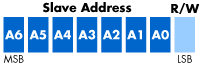
Figure 1: 7-bit addressing. The I2C bus specification specifies that in standard-mode I2C, the slave address is 7-bits long followed by the read/write bit.
All I2C products from Total Phase, follow this standard convention. The slave address used should only be the top seven bits. In the case of the Aardvark I2C/SPI Host Adapter, the software will automatically append the correct read/write bit depending on the transaction to be performed. In the case of the Beagle I2C/SPI Protocol Analyzer, the slave address and the type of transaction are displayed in two different columns.
Reserved Addresses
The I2C specification has reserved two sets of eight addresses, 1111XXX and 0000XXX. These addresses are used for special purposes. The following table has been taken from the I2C Specifications (2000).
| Slave Address | R/W Bit | Description |
| 000 0000 | 0 | General call address |
| 000 0000 | 1 | START byte(1) |
| 000 0001 | X | CBUS address(2) |
| 000 0010 | X | Reserved for different bus format (3) |
| 000 0011 | X | Reserved for future purposes |
| 000 01XX | X | Hs-mode master code |
| 111 10XX | X | 10-bit slave addressing |
| 111 11XX | X | Reserved for future purposes |
(1) No device is allowed to acknowledge at the reception of the START byte.
(2) The CBUS address has been reserved to enable the inter-mixing of CBUS compatible and I2C-bus compatible devices in the same system. I2C-bus compatible devices are not allowed to respond on reception of this address.
(3) The address reserved for a different bus format is included to enable I2C and other protocols to be mixed. Only I2C-bus compatible devices that can work with such formats and protocols are allowed to respond to this address.
8-bit Addresses
Some vendors incorrectly provide 8-bit addresses which include the read/write bit. Often, you can determine if this is the case because they will provide one address for writing to the slave device and another to reading from the slave. In this situations, use the top seven bits of the address only.
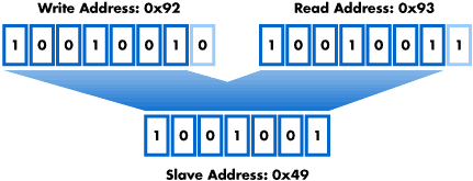
Figure 2: 8-bit addresses. Some vendors incorrectly provide two 8-bit slave addresses for their device, one to write to the device and one to read from the device. This 8-bit number actually encodes the 7-bit slave address and the read/write bit. Since Total Phase's products use 7-bit addressing, it is important to only use the top 7 bits of the address as the slave address.
Another way to determine if a vendor is using 8-bit addresses instead of 7-bit addresses is to see if the slave address falls within the correct range. All 7-bit addresses should be greater than 0x07 and less than 0x78 (120). If your slave address is outside this range, chances are your vendor has specified an 8-bit address.
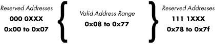
Figure 3: Valid 7-bit Slave Address Range. The range of valid 7-bit slave addresses are bound by two blocks of reserved addresses at either end of the range. Valid slave addresses are greater than 0x07 and less than 0x78.
10-bit Addressing
One of the reasons that Total Phase decided to use 7-bit addressing for all of its products was to ensure that 10-bit addressing could be properly handled.
10-bit addressing was designed to be compatible with 7-bit addressing, allowing developers to mix two types of devices on a single bus. When communicating with a 10-bit addressed device, the special reserved address is used to indicate that 10-bit addressing is being used.
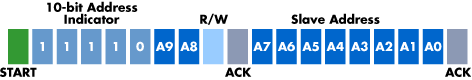
Figure 4: 10-bit addressing. In 10-bit addressing, the slave address is sent in the first two bytes. The first byte begins with the special reserved address of 1111 0XX which indicates that 10-bit addressing is being used. The 10 bits of the address is encoded in the last 2 bits of the first byte and the entire 8 bits of the second byte. The 8th bit of the first byte remains the read/write flag.
If a 10-bit address is specified when using the Aardvark I2C/SPI Host Adapter, its software will take care of sending the correct bits. The developer does not need to perform any special steps to send the correct address data. The Beagle I2C/SPI Protocol Analyzer will also automatically detect 10-bit slave addresses in the captured data and display the information correctly.
References
- I2C-bus Specification and User Manual - NXP
- Totalphase.com
See also how to trigger on slave address.
