Introduction
ScanaQuad Logic Analyzers and pattern generators have a versatile I/O stage, that allows the user to configure the probes in various different fashions, covers a broad range of applications.
In this tutorial, we’re going to present the different probes configuration options and their usage. We’re going to assume you’re using an SQ200 Logic analyzer. Depending on the model you own, not all features may be available.
Probes configuration
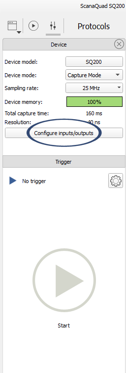
ScanaQuad probes configuration can be accessed by clicking on the “Configure inputs/outputs” button in ScanaStudio software, as show in the image below:

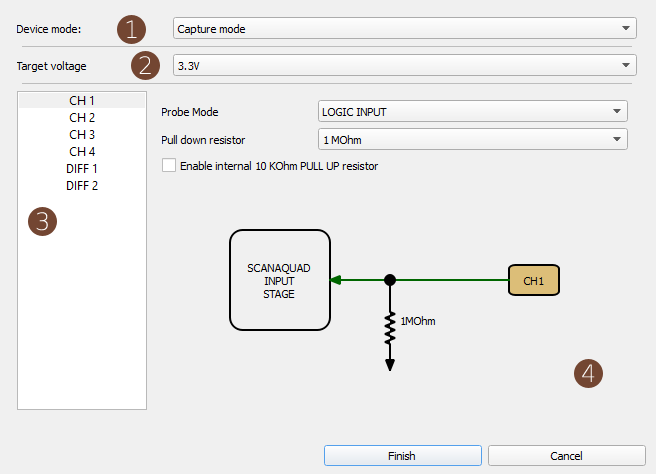
You should then see the configuration window as shown below:

This window is composed of 4 main element:
-
The device mode.
Here you can select between 4 modes: Capture, Generate loop, Generate Once and Mixed mode. Capture mode is the regular “logic analyzer” operation mode, where signals are captured then sent to computer for display. Generator modes, as the name implies, is used to generate logic patterns. Mixed mode, well, can do both simultaneously.
-
Target voltage.
The target voltage applies to all 4 channels and cannot be different for each channel. For best results, you need to select a target voltage that is as close as possible to the logic voltage of the system being tested. There’s two ways of understanding the meaning of target voltage. First, if we’re capturing signal, choosing a target voltage will allow ScanaQuad to know where to to set the logic level thresholds. Then, if we’re generating signals, setting the target voltage will effectively set the logic level of generated signals.
-
Channel selection field
This lets you select one channel to further configure.
-
Channel configuration.
In this part of the window, you can configure the channel selected in section 3.
Let’s now concentrate on the various options that can be configured for each channels.
-
First you should use the “probe mode” drop down box to select a predefined mode. This is a list of possible applications. clicking on of them will automatically configure the other parameters of a channel. It’s a like a shortcut or a template. For example, selecting the probe mode as “I2C I/O” will automatically enable the 10KΩ pull up resistor, set the probe as open drain, and set pull down resistance to its maximum value.
-
Then, you may further “fine tune” some parameters according to your application. Suppose you’re debugging and I2C line that already has it’s pull up resistors. You don’t want ScanaQuad to add any additional “pull up” current to the circuit, so you can deactivate the 10KΩ pull up resistor.
-
Finally, you may want to use differential pairs. Differential pairs are used to interface with differential signaling logic systems (Read more about that here). This can be an RS232 interface, a CAN data BUS, an LVDS pair, or any differential signaling withing the specifications of ScanaQuad.
Important note:
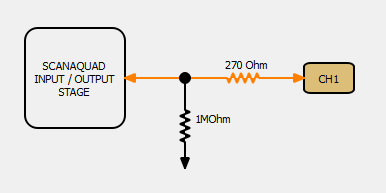
You’ll notice that when a probe is configured as OUTPUT, a 270Ω is added in series of the probe. It is important to take that resistance into consideration when driving circuits with ScanaQuad.

This current limiting resistors basically means that ScanaQuad cannot source much current, and that’s fine if you’re connecting ScanaQuad’s outputs to a high impedance input. This should be the case 99% of the time. If you’re connecting ScanaQuad’s output to a low impedance input, draining current from ScanaQuad, then you’re probably doing something wrong, and that 270Ω resistor is here to protect both ScanaQuad and your equipment. If you need to connect ScanaQuad to a device that sinks some current (like a high power LED or a motor), then you should use some buffer or driver in-between ScanaQuad and the device. However, you can directly connect ScanaQuad output to servo motor control input, I2C lines, UART data line, Audio amplifier inputs, etc…
Conclution
ScanaQuad Logic Analyzer’s probes can be configured in many different ways. This allows ScanaQuad to cover a broad range of applications. However, some configuration parameters may be confusing for some users. This tutorial aims to demystify different options and parameters used to configure probes.


